
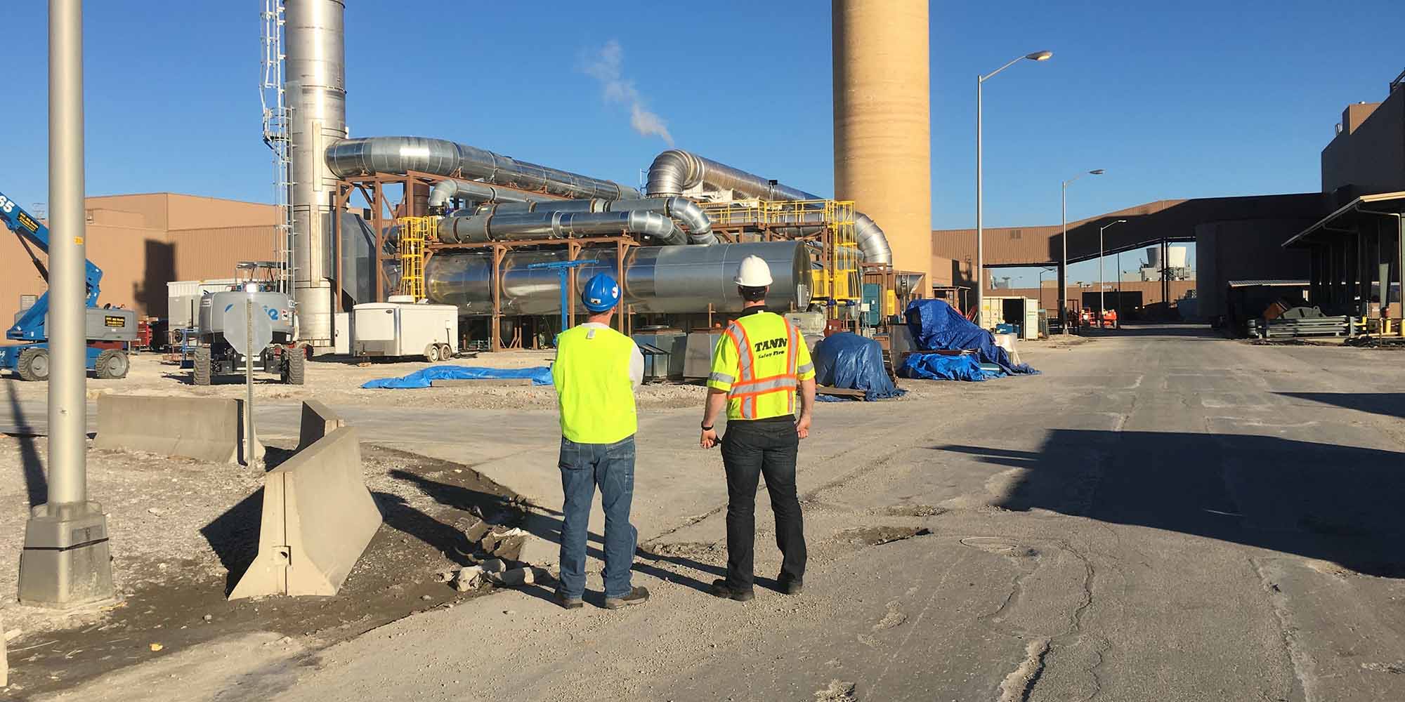
Regenerative catalytic oxidizer (RCO) technology occupies a specific place in industrial air pollution control. It pairs the ceramic heat recovery that makes regenerative systems so fuel efficient with a catalyst bed. That bed allows oxidation at much lower temperatures. For facilities with the right exhaust profile, that combination delivers real fuel savings and a smaller carbon footprint. For many others, a regenerative thermal oxidizer (RTO) remains the better long-term choice.
Because the two technologies share so much architecture, the decision between them comes down to the exhaust stream itself. Volatile organic compound (VOC) concentration, exhaust chemistry, and particulate loading determine which system will perform reliably for decades. Neither spec sheets nor sales pitches settle that question. The exhaust data does. In this guide, we explain how a regenerative catalytic oxidizer works and where it fits. We also cover how its economics play out over the life of the equipment, along with the catalyst lifecycle questions every buyer should ask before committing to the technology.
What Is a Regenerative Catalytic Oxidizer?
In structural terms, an RCO looks almost identical to an RTO. Both use ceramic media beds to capture heat from outgoing clean air and transfer it to incoming process exhaust. A regenerative catalytic oxidizer destroys VOCs at approximately 800 degrees F by passing preheated exhaust over a catalyst bed, far below the approximately 1,500 degrees F that thermal oxidation requires. The catalyst does the work that raw temperature would otherwise do. In addition, the ceramic beds recover most of the combustion heat before it leaves the stack. Together, those two features define the technology’s efficiency case.
Inside the unit, a layer of catalyst material sits above the ceramic heat exchange media. When preheated exhaust reaches that layer, the catalyst accelerates the oxidation reaction. VOC molecules break down into carbon dioxide and water vapor at a fraction of the thermal setpoint. Catalytic oxidizer systems use precious metal or base metal catalysts to lower the temperature at which VOC destruction occurs. Since the burner has far less heating to do, fuel consumption drops accordingly.
Terminology in this space overlaps, which causes confusion during equipment research. Some sources use catalytic thermal oxidizer as a catch-all for any catalyst-based system. In practice, the regenerative prefix is the part that matters. While a standard catalytic unit recovers heat through a metal exchanger, an RCO stores it in ceramic media beds the way an RTO does. That distinction drives the efficiency numbers that follow.
When a facility asks us whether an RCO fits their process, we start with an exhaust sample, not a spec sheet. Our engineers look at VOC species, concentration, and contaminants before recommending any catalytic approach.
How a Regenerative Catalytic Oxidizer Works
The operating cycle of a regenerative catalytic oxidizer follows the same regenerative logic as an RTO. The catalyst layer simply sits at the top of each media bed. Understanding the sequence makes the fuel advantage obvious.
The Process, Step by Step
- Inlet preheat: Process exhaust enters through an inlet media chamber and absorbs heat stored in the ceramic media. Each cycle banks that energy for the next one. By the time the air reaches the catalyst, it’s already close to reaction temperature.
- Burner trim: A burner raises the air stream to the catalytic setpoint of approximately 800 degrees F. Because the setpoint is low and the preheat is efficient, the burner often runs at minimal firing rates.
- Catalytic oxidation: The exhaust passes through the catalyst bed, where VOCs oxidize into carbon dioxide and water vapor on the catalyst surface.
- Outlet heat recovery: The cleaned air transfers its heat back into the outlet ceramic media bed before discharge, storing energy for the next cycle.
- Flow reversal: After a timed interval, valves reverse the airflow direction. The former outlet chamber becomes the inlet chamber, and the cycle repeats continuously.
Anyone familiar with regenerative thermal oxidizer operation will recognize every step except the catalyst layer. The regenerative heat exchange cycle allows both RCO and RTO systems to recover most of their combustion heat instead of exhausting it to the atmosphere. As a result, both technologies achieve strong thermal efficiency; the RCO simply needs less heat in the first place.
Valve performance deserves attention in any regenerative design. Each flow reversal briefly redirects untreated air, so valve sealing quality and switch timing directly affect destruction efficiency. Similarly, the condition of the ceramic media determines how much preheat the catalyst receives. Well-maintained media keeps the burner load low. Degraded media forces the burner to make up the difference.
Before we configure any regenerative system, our engineers model the media depth, valve timing, and heat balance against the facility’s actual operating schedule. Getting those variables right at the design stage protects efficiency for the life of the unit.
RCO or RTO: Matching the Technology to the Exhaust Stream
Neither technology is universally better. Each earns its place based on what’s in the exhaust stream, and an honest evaluation starts there rather than with a product preference.
Where the RTO Remains the Default
For most industrial applications, the RTO is the proven default, and for good reasons. Regenerative thermal oxidizer systems handle particulate-laden exhaust, tolerate a wide range of VOC chemistries, and operate reliably for 20-30 years without catalyst replacement risk. High thermal oxidation temperatures destroy virtually any organic compound. As a result, the technology forgives process changes over time.
That flexibility matters over a multi-decade service life. Production lines change, coatings get reformulated, and exhaust chemistry shifts. An RTO keeps performing through all of it. No catalyst means nothing to poison, nothing to mask, and one less consumable in the maintenance budget. For plants that can’t predict what their exhaust will look like in ten years, that certainty has real value. Most importantly, it removes an entire failure mode from the compliance picture. Facilities running processes with particulate, silicone compounds, or variable exhaust chemistry are almost always better served by thermal oxidation.
Where an RCO Earns Its Place
The RCO case is narrower but genuine. Regenerative catalytic oxidizer systems fit best on clean exhaust streams with low VOC concentrations and no catalyst-poisoning compounds such as halogens, sulfur, silicones, or heavy particulate. In that window, the lower operating temperature translates directly into lower fuel demand, month after month.
Dilute exhaust streams are the sweet spot. When VOC concentrations are too low to contribute meaningful combustion heat, a burner must supply nearly all of the required energy. For an RTO, that means firing to approximately 1,500 degrees F. Under the same conditions, an RCO reaches its reaction temperature with far less firing. Consequently, the facilities that benefit most are those whose streams demand the hardest burner duty.
Candidate applications share a recognizable profile. Clean solvent streams from printing, coating, and converting operations often qualify when the process generates no particulate and no silicone compounds. Even then, the stream chemistry needs verification before anyone orders a catalyst bed. One reformulated coating containing silicone can shorten catalyst life dramatically.
Instead of steering clients toward one technology, our engineers evaluate the exhaust profile first and recommend the system that will still be the right answer in year fifteen. Sometimes that’s an RCO. More often, it’s an RTO, and we’ll tell you which and why.
RCO Economics: Fuel Savings, Carbon Footprint, and Break-Even
The economic argument for a regenerative catalytic oxidizer rests on one physical fact. Heating air to approximately 800 degrees F takes far less fuel than heating it to approximately 1,500 degrees F. Lower oxidation temperature reduces supplemental natural gas consumption, which lowers both monthly operating cost and the facility’s combustion-related carbon footprint. Every therm of gas not burned is money saved and carbon dioxide never emitted. Therefore, the fuel line item drives the entire comparison.
Electricity costs stay roughly comparable between the two technologies. Both use a main system fan sized to the same airflow, and both cycle valves on similar schedules. Consequently, the economic comparison between an RCO and an RTO is fought almost entirely on fuel. Whichever system burns less gas for a given stream wins the operating cost battle.
Sustainability targets make that second benefit increasingly relevant. Many manufacturers now report scope 1 emissions. Pollution control equipment that runs a burner around the clock shows up in those numbers. An RCO lowers a facility’s carbon footprint by cutting the supplemental fuel burned to maintain oxidation temperature. For EHS teams balancing compliance obligations against emission reduction goals, that dual benefit is worth quantifying.
The 7-8 Year Break-Even
The catalyst bed adds real capital cost on top of RTO-equivalent architecture. Therefore, the fuel savings have to earn it back. In a well-matched application, the RCO’s higher upfront cost is recovered through fuel savings versus a comparable RTO in 7-8 years of operation. After the break-even point, the fuel advantage accrues to the bottom line for the remainder of the equipment’s service life. For example, a system crossing break-even in year eight still has well over a decade of savings ahead of it on a typical service life.
Two caveats keep that math honest. First, the break-even assumes the application actually fits. That means a clean, dilute stream where the RTO alternative would run significant supplemental fuel. Second, catalyst replacement over the system’s life belongs in the projection. It’s a recurring cost an RTO doesn’t carry. For a detailed look at how fuel, electricity, and maintenance interact over decades of ownership, see our guide to RTO operating costs.
Before any client commits to catalytic technology, our engineering studies project the full ownership comparison. We build it on your actual gas rates and operating hours. A break-even estimate built on your data beats an industry average every time.
Catalyst Lifecycle and Maintenance Planning
The catalyst is the RCO’s defining component and its defining maintenance obligation. Unlike ceramic media, catalyst material gradually loses activity even in clean service. Certain compounds accelerate that decline sharply.
Halogenated and sulfur compounds act as catalyst poisons, permanently reducing activity. Meanwhile, particulate and silicone compounds can mask the catalyst surface. Masking blocks contact between the exhaust and the active material. Catalyst degradation reduces destruction efficiency gradually, which makes periodic catalyst sampling and activity testing essential for maintaining compliance on any RCO system. Without testing, a facility usually discovers the problem through a failed compliance test rather than a maintenance report.
However, none of this makes an RCO a fragile system. On a properly matched exhaust stream, catalyst service life runs for years, and testing turns replacement into a planned expense rather than a surprise. Budgeting for the catalyst belongs in the purchase decision, not the year it fails. Replacement intervals vary with the application, and clean service extends them considerably. Sensible lifecycle planning treats the catalyst like the consumable it is. Periodic activity testing establishes the degradation trend. Replacement timing then follows the data rather than a guess. In addition, the ceramic heat exchange media beneath the catalyst follows the same inspection logic as any regenerative system. When a client’s catalyst starts showing reduced activity, we assess the remaining usable life against their compliance margin. Our replacement recommendations follow actual test data, not a calendar schedule.
Final Thoughts
The regenerative catalytic oxidizer isn’t a competitor to the RTO so much as a specialist within the same family. It wins in one clearly defined window: clean, dilute exhaust streams where lower temperature converts directly into fuel savings. In that window, the payoff includes a smaller carbon footprint and a break-even in 7-8 years. Outside that window, the RTO’s chemistry tolerance and freedom from catalyst risk keep it the default for a reason.
If your exhaust stream is low in VOC concentration and free of catalyst poisons, the RCO comparison is worth running with real numbers. Bring us your exhaust data and gas rates, and we’ll model both technologies against your actual operating profile. The decision should rest on evidence rather than assumptions.
TANN Corporation has designed and manufactured regenerative thermal oxidizer systems for 40+ years, serving manufacturers across every industry with VOC compliance requirements. Our engineering team evaluates each application individually, recommending system configurations optimized for specific exhaust characteristics and compliance obligations. From initial assessment through installation and decades of ongoing support, we deliver complete emission control solutions. Contact us today for a free quote or to learn more.